Drawing Angles using Protractor
How to Draw an Angle using a Protractor
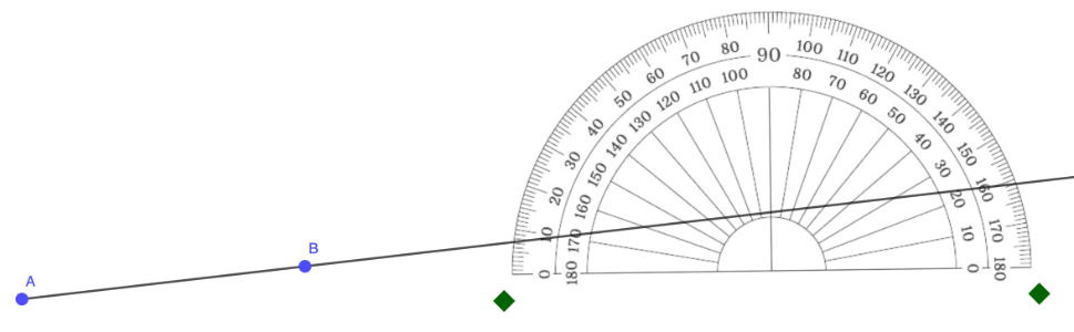
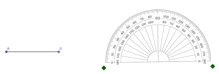
Step 1: Draw a ray that will serve as one of the rays (or side) of the angle.
In the example below, ray AB is one of the rays of the angle.
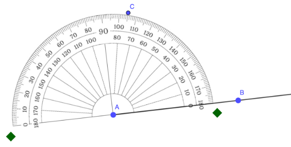
Step 2: Place the center of the protractor on the vertex of the angle.
In the example below, the center of the protractor was placed in point A.
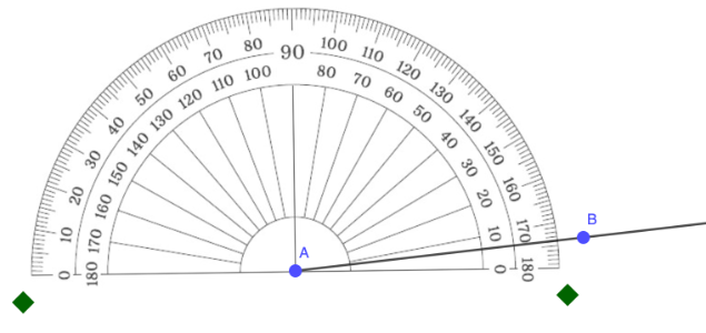
Step 3: Align the baseline of the protractor with one ray (side) of the angle.
In the example below, the baseline was aligned with side AB.
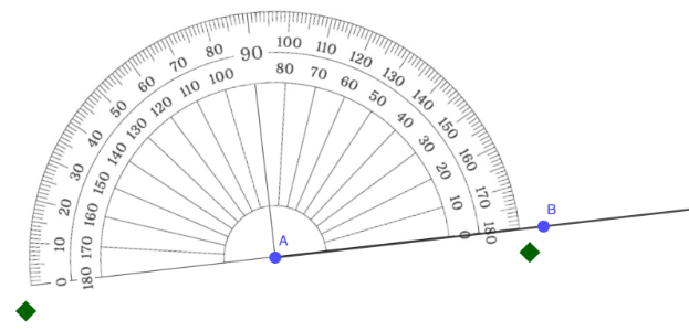
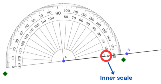
Step 4: Match the 0° mark on the appropriate scale of the protractor with the ray (or side) you aligned in step 3.
In the example below, the 0° mark where the ray is located is on the inner scale.
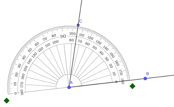
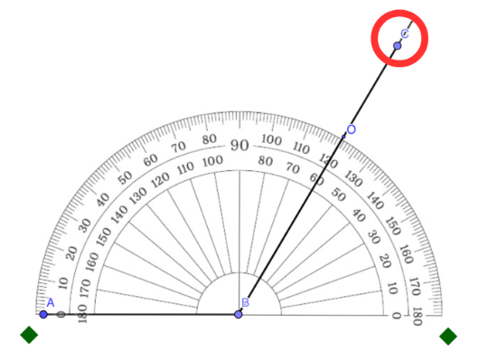
Step 5: Starting from the 0° mark, follow the rotation from the ray positioned in Steps 3 and 4. Identify the measure of the angle to be constructed and mark that point.
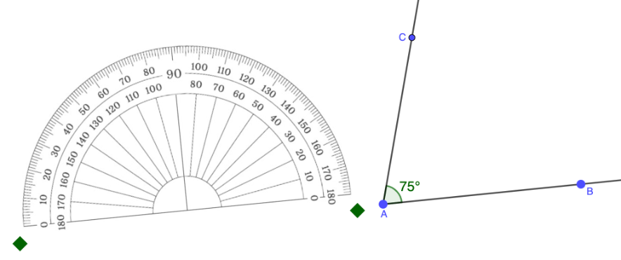
In the example below, the angle to be constructed measures 75°, with the point C indicating its location.
Step 6: Draw a ray passing through the vertex and the point marked in Step 5.
How to Draw an Angle Given Line Segment Lengths Using a Protractor
Step 1: Use a ruler to draw a straight line segment of the given length. Label the endpoints as A and B.
In GeoGebra, you can use the Segment with a Given Length tool.  In the example below, the length of the segment is 5 units.
In the example below, the length of the segment is 5 units. 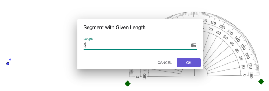
Step 2: Place the center of the protractor on the vertex of the angle.
In the example below, the center of the protractor was placed in point B, as it is set as the vertex of the angle.
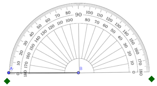
Step 3: Align the baseline of the protractor with one ray (side) of the angle.
In the example below, the baseline was aligned with side AB.
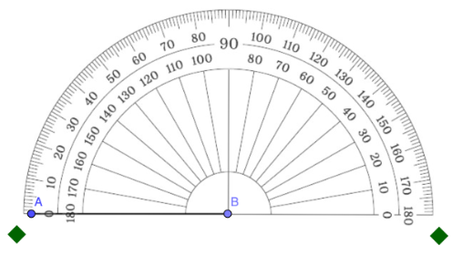
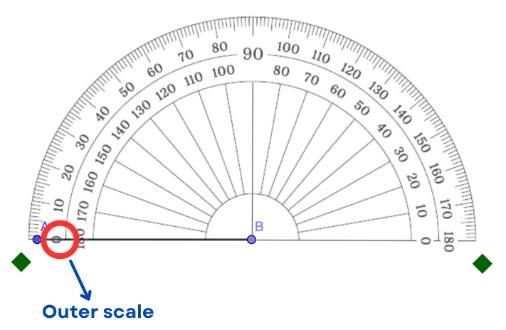
Step 4: Match the 0° mark on the appropriate scale of the protractor with the ray (or side) you aligned in step 3.
In the example below, the 0° mark where the ray is located is on the outer scale.
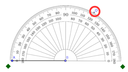
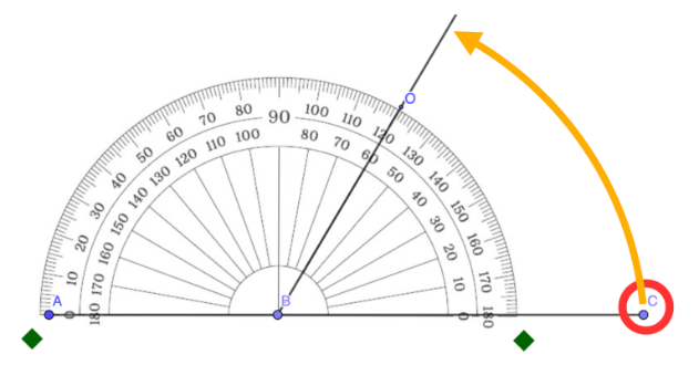
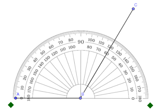
Step 5: Starting from the 0° mark, follow the rotation from the ray positioned in Steps 3 and 4. Identify the measure of the angle to be constructed and mark that point. Note that this point is a temporary mark only.
In the example below, the angle to be constructed measures 120°, with the point O indicating its location.
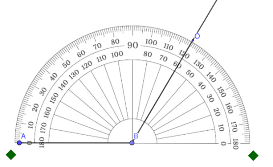
Step 6: Align the ruler so that it passes through the vertex and the temporary mark from Step 5. Draw a straight line. . Note that this is a temporary line only.
In GeoGebra, you can use the Ray tool. 
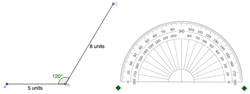
Step 7: On the temporary line in Step 6, draw a straight line considering the given length of the second segment.
In GeoGebra, utilize the Segment with a Given Length tool. Drag the endpoint of the constructed segment to align it with the temporary line from Step 6.
In the example below, the length of the segment is 8 units.
tool. Drag the endpoint of the constructed segment to align it with the temporary line from Step 6.
In the example below, the length of the segment is 8 units. 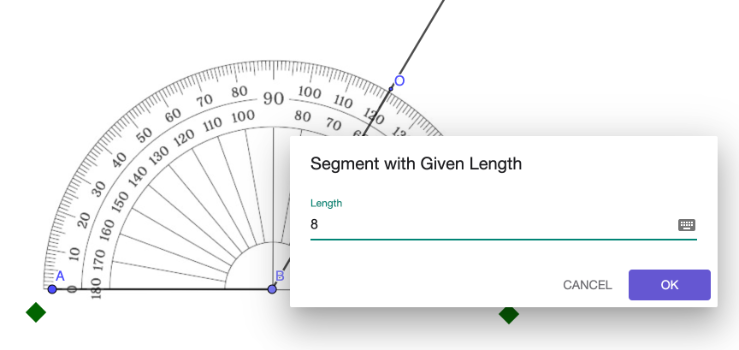
Step 8: Erase the temporary marks.
Practice #1
Draw a 145° angle.
Practice #2:
Draw an 80° angle with side lengths of 4 units and 6 units.